
3 Prerequisites To Establishing An Environmental Monitoring Sampling Plan
By Allan Marinelli, Quality Validation 360 Inc.

This article is the first in a three-part series describing an engineering approach to establishing an environmental sampling plan for a new pharmaceutical or biopharmaceutical manufacturing facility. The series assume the facility has just been built and no manufacturing of batches have been run, despite being associated with other corporate sites. Simulations of dynamic conditions analogous to producing a batch will be factored in. This article will cover phase 1 in the development of such a sampling plan, and future installments will cover phases 2 through 6.
A Six-Phase Approach
Within the pharmaceutical and biopharmaceutical industries, putting together an effective environmental sampling plan with respect to the performance qualification (PQ) can be cumbersome if not organized in respective phases. As part of the validation documentation, often the PQs are the first set of documentations that can be inspected by the FDA or other regulatory agencies. It is suggested — but not restrictive nor exhaustive — to capture six phases, as shown in Figure 1.
It is important to note that the extent of assimilating the phases is commensurate with the risk of the manufacturing process applications controlled under the relevant regulatory agencies and intended uses. I provided a generic example of the elements suggested to attain successful regulatory inspections, but companies may need more or less planning.
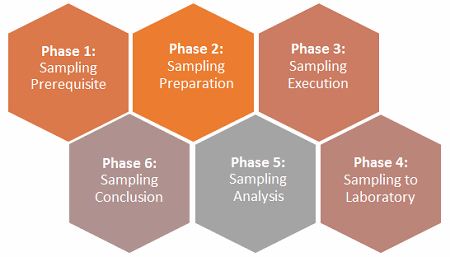
Figure 1: The six phases of an environmental monitoring (EM) sampling plan
Phase 1: Sampling Prerequisite Phase
Prior to establishing an environmental sampling plan, there are three recommended prerequisites:
- Engineering baseline testing:
- Heating, ventilation, and air conditioning (HVAC) balancing report
- HVAC installation qualification (IQ)
- HVAC operational qualification (OQ)
- HVAC PQ
These must be successfully completed prior to commencing the initial projective plan.
- Initial projective plan
- A risk analysis coupled with engineering baseline data to determine the sampling points
Please note that the word “user” is intended to generically signify the designee representing the company who is responsible in putting together an environmental monitoring sampling plan.
The following steps describe are recommended for the reader to consider in alignment with their company’s user requirement specifications, business models, quality manual, and corporate environmental monitoring program/validation plans.
Step 1: Engineering Baseline Testing
The first step in this phase is to ensure the following is in place prior to conducting any environmental planning, etc.
The HVAC system must be balanced by the vendor that originally set it up prior to conducting any validation of the system. Moreover, the user must understand the balancing report and ensure the pressures and flows are aligned or within the design range of the system.
The user must perform an IQ of the HVAC system. This entails the following tests, but this is not an exhaustive nor a prescriptive list:
- Verification of air handler units (AHUs) test: Verify the manufacturer, model number, nominal tons, air capacity, and location.
- Verification of humidifier and reheat coils test: Verify the manufacturer, model number, nominal tons, capacity, and location.
- Verification of utilities: Verify the incoming voltage, amperage, etc.
- Verification of instrumentation/calibration test: Verify the temperature control units, pressure control gauges/instruments, and relative humidity gauges/instruments.
- Verification of drawing walk-down system test
- Verification of documentation list
The user also must perform an OQ of the HVAC system. This entails the following tests, but this is not an exhaustive or prescriptive list:
- Air flow check (cubic feet per minute) and temperature check for each AHU test: You can use the values from the testing and balancing report in combination with actual measurements in the field to confirm the measured results fall within the air flow and temperature design operating range at the time of executing the protocol.
- Shut down and recovery test: Record the time the system takes to recover and operate within normal functional environmental conditions and HVAC throughput.
- Pressures test: Record actual pressure measurements in the field using calibrated devices/gauges as a function of room classification, and ensure the actual results fall within the pressure design operating range of the system.
- Temperature and relative humidity as a function of room classification: Record actual temperature/relative humidity measurements in the field using calibrated devices/gauges as a function of room classification, and ensure the actual results fall within the temperature/relative humidity design operating range of the system.
- HEPA filter certification (manufacturer’s official tested results before reaching the user), including post-installation filter integrity test at the user’s site
- Room air flow direction verification: Record actual room air flow direction by visually observing the direction of smoke coming from the smoke generator or smoke stick in the field as a function of room classification. The actual (field) flow smoke direction relative to the entrance/exit doors of the room of interest must flow in the expected direction between the adjacent rooms in congruence with your room air flow direction drawing.
- Room air change verification: Record actual room air change measurements in the field using calibrated devices/gauges as a function of room classification, and ensure the actual results fall within the design range of the system.
- Room particulate verification: A baseline room particulate verification can be done under static conditions to ensure the system is ready to proceed to PQ if all results meet specification requirements for air-non-viable, air-viable, and viable surfaces.
The user must perform a PQ of the HVAC system. This entails the following tests, but this is not an exhaustive or prescriptive list:
- Room pressurization verification
- Room temperature and humidity verification (dynamic versus static)
- Particulate verification: Three static periods versus three dynamic periods pertaining to air-non-viable (>0.5 µM and 5 µM), viable (airborne), and viable surface (wall, floor, equipment/miscellaneous). Note that since the facility had never produced product at this point, dynamic conditions at this stage are intended to simulate an actual batch production by having many interventions and various operators working in the cleanroom (grade C, B, or A classifications).
Step 2: Initial Projective Plan
An initial projective plan, which defines the scope, boundary, and work/time projection, should be in place before seeking approval from management to proceed with a formal risk analysis. Once management reviews and grants the authorization to proceed, a cross-functional team should be selected. At a minimum, it should include:
- Project manager
- Subject matter experts (SMEs): The relevant SME can be selected per area of sampling. For example, an SME who is a process expert in the purification suite can be selected to decipher the potential worst-case traffic area within the suite to include all EM sample locations relative to viable, non-viable, particulate samples, etc.
- QA
- Microbiologist
- Risk assessor
- “Other” as defined in the company’s SOP or policy, as applicable.
Step 3: Conducting A Risk Analysis
When conducting a risk analysis, factor in worst-case conditions in conjunction with brainstorming sessions, what-if analysis, and determination of the highest impact of microbiological or non-viable particulate contamination for the room of interest (conducted by the relevant SMEs for the specific area). The following considerations are recommended:
- Decipher and establish all processes relative to the design and intended uses.
- Look at the facility design drawings and determine the path direction of personnel and materials for each flow diagram using process flow diagrams (PFDs), piping and instrumentation diagrams (P&IDs), etc.
- If available, combine the data from (a) and (b) with historical static baseline testing and dynamic EM testing results for a site that is architecturally equivalent, but not identical, to the current site.
- Itemize the potential variables (people, process, batch, equipment malfunction such as HVAC, disaster recovery conditions, power outages, etc.) which can result in potential contamination within the room in question (e.g., purification room) and adjacent rooms.
- Identify the potential frequency of occurrence for each event.
- Determine the potential activity level by rating them as a function of room classification. For example, a high activity in grade A/B, ISO 5, or Class 100 will not be evaluated equivalently as the same event in grade C, ISO 7, or Class 10,000.
- Establish the potential timeline for the event while factoring in engineering controls such as the efficiency throughput of the HVAC system.
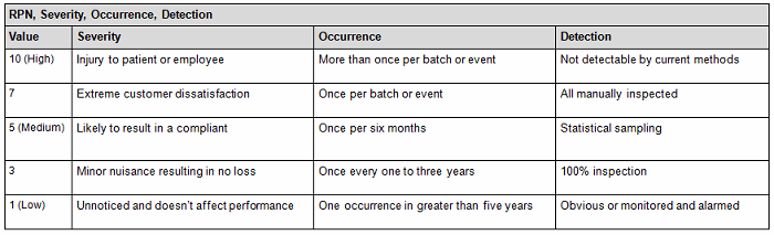
a. Assess the probability that the limits may be exceeded beyond the acceptance criteria by using a quantitative method (Tables 1A and 1B), assigning a risk priority number (RPN) as indicated by the following equation: RPN = S (severity) x O (occurrence) x D (detectability).
Table 1A: Quantitative Risk Assessment1
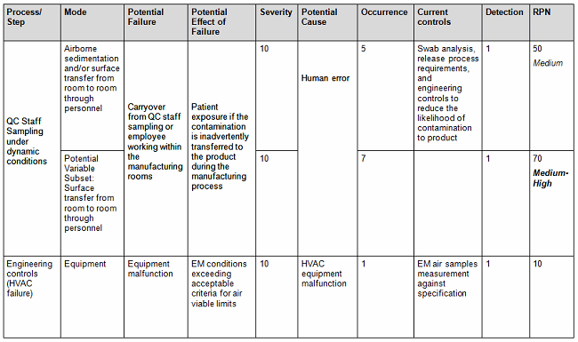
Table 1B: Sample of Failure Modes and Effects Analysis (FMEA) Scoring Criteria1
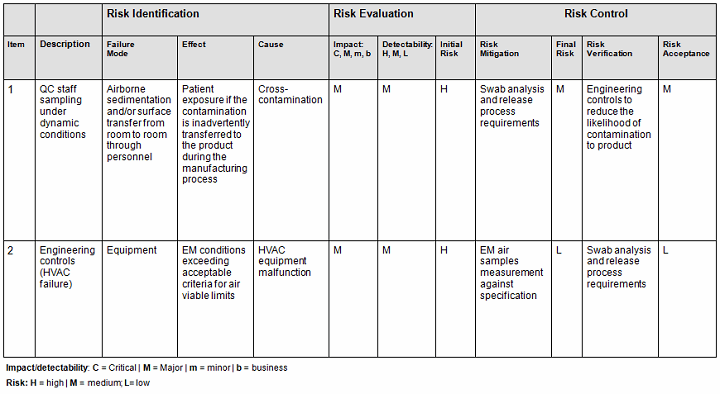
- Conversely, you can also use the qualitative method (Table 2), but it is not as accurate since it is intended to be used as an estimate or approximation in deciphering the risk level by using a color criteria. For example, any event evaluated as green (acceptable or low risk) is automatically classified as acceptable without consideration of the other potential variable subsets. The quantitative method would have easily captured the next-highest risk level since by default this method encompasses the potential variable subset risks, thereby potentially changing the actual outcome from medium to medium-high (the next risk level). See item 1 in Table 1 A versus Table 2 to capture this point.
Table 2: Qualitative Risk Assessment1,2
- Determine the total number of samples to be tested in alignment with the regulations and the company’s user requirement specifications relative to room classifications and sample locations. Based this number on data obtained from (a) to (d) including data from HVAC air flow direction testing, HVAC room change rate verification, HVAC room pressurization verification, HVAC temperature/relative humidity verification, and HVAC balancing report data. Bear in mind that some site locations may not be accessible to sample. In that case, you would need to determine whether the selected hardest-to-sample represent the same hardest-to-clean/sanitize areas and, if so, ensure at least one or two samples are tested in these areas over and above the conclusion of the risk assessment.
- Note: If the HVAC balancing report is not complete, it can be mentioned to ensure the recommended test is captured within the HVAC validations. Moreover, in determining the sample location, you would need to determine what kind of sample to prepare/take relative to the room classification and intended uses. For example, you may need to prepare air samples for microorganisms and/or non-viable particulate or surface samples or all as mentioned.
- The type of samples to be determined is contingent upon the room classifications. For example, for Grade A/B formulation production rooms, ISO 5, or Class 100, you would need non-viable in air (particles), microorganism in air, and surface.
a. Based on the input from the SMEs and cross-functional team, draft the following EM drawings toward final approval:
- Surface viable samples drawing: The drawing would show the floor, wall, and miscellaneous samples, including the specified locations to be tested.
- Non-viable particulate samples drawing: The drawing would show non-viable air samples, including the specified locations to be tested.
- Viable air particulate samples drawing: The drawing would show viable air particulate samples, including the specified locations to be tested.
- A risk assessment report containing the stakeholder’s name and department, specifics of the cross-functional team members, and a description of the analyzed items/total samples required to be tested relative to the room classifications and corresponding documentation is recommended. Also include in the report a conclusion that describes where to take the samples and which type of samples.
- Note: After completing the risk assessment report, document this information into a change log to capture all potential alterations or changes during the life cycle.
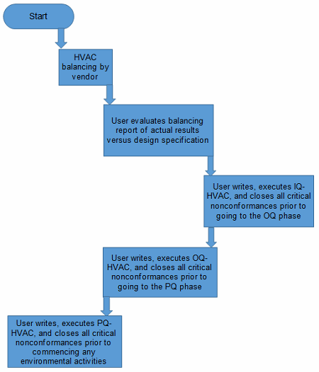
Figure 2: Flowchart prior to conducting sampling preparation phase
The next article in the series will discuss phases two and three of the engineering approach to establishing an environmental sampling plan.
References:
- ISPE Baseline, Volume 7, Risk-Based Manufacture of Pharmaceutical Products, 1st Edition/September 2010, Page 92 to 94
- Allan Marinelli, “A Workable Sampling Plan Using a Quality Risk Management Approach Relative to the PQ Phase of the Upgraded Purified Water Generation System at the Pilot Plant/Small Scale Level-A Validation Engineering Perspective,” Journal of Validation Technology (JVT) and Network, 18 Jun 2014
Note: A version of this article will appear in an upcoming revision of the book Environmental Monitoring: A Comprehensive Handbook, to be published by the PDA/DHI (Parenteral Drug Association / Davis Healthcare).
About The Author:
 Allan Marinelli acquired over 25 years of worldwide cGMP experience in Belgium, France, South Korea, China, India, Canada, the U.S. under the FDA, EMA, SFDA, KFDA, WHO, and other regulators. He is currently the president/CEO of Quality Validation 360 Incorporated, providing consultation services to the (bio)pharmaceutical, medical device, vaccine, and food/beverage industries. Marinelli has authored peer-reviewed papers (Institute of Validation Technology) and chapters on validation, risk analysis, and environmental monitoring in PDA/DHI books, and chapters on cleaning validation in PDA/DHI books. In addition, Marinelli published peer-reviewed articles on Pharmaceutical Online, Bioprocess Online, and Outsourced Pharma in 2016, 2017, and 2018. He is an associate member of ASQ (American Society for Quality) and published an article in ASQ titled “Against the Grain, Standing your ground when senior majority rules” in Quality Digest (Aug. 2014). He may be contacted at amarinelli360@gmail.com.